
This guide explains step-by-step how I built a Fuzz Factory clone from a kit.
Even if you’re not interested in building your own Fuzz Factory pedal, this guide is a great way to learn what is involved in building guitar pedals.
You can use this guide as a general blueprint to follow for any DIY guitar pedal build. Learn about best practices and avoid the mistakes I made along the way.
Check out my Ultimate Guide to Building Guitar Pedals to learn about the tools, hardware, kits, and steps involved in building any guitar pedal.
This guide is part of my series of guides, videos, and tutorials on building your own guitar pedals. To stay up to date on future guides, subscribe to email updates here.
If you want to learn about Fuzz effects, check out my Ultimate Guide to Fuzz here.
Fuzz Factory Clone Kit
The kit I built is this Berserker Fuzz Kit from DIY Guitar Pedals in Australia (they ship worldwide).
I highly recommend the Berserker Fuzz kit if you’re interested in building a Fuzz Factory clone. The kit and all of the other kits on the DIY Guitar Pedals website are very well made and Paul from the site provides excellent support.
Tip: if you want to buy this kit from outside of Australia, buy your pedal enclosure (1590B) separately from anywhere in your country. This will save you on shipping costs.
The Berserker Fuzz is a modified version of the Fuzz Factory and adds a tone knob to the circuit.
The Fuzz Factory by ZVEX Effects is an iconic fuzz pedal due to the crazy variety of fuzz tones you can get from it. You can dial in anything from a subtle fuzz all the way to unusably-weird oscillating sounds. Surprisingly-fun velcro-like sounds and some odd octave effects make the Fuzz Factory an iconic pedal.

The original Fuzz Factory gives you five knobs that loosely match the labels they’re given: Volume, Gate, Compression, Drive, and Stability.
These knobs interact with each other, which means the Fuzz Factory can be confusing at first to control. But after some experimenting, you eventually learn what the knobs actually do to your guitar tone.
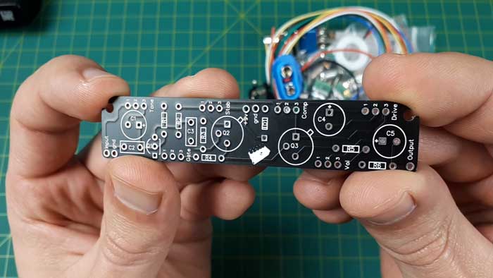
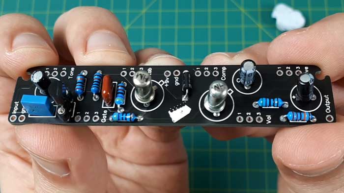
As you can see from the above photo of the Berserker Fuzz PCB, it’s a simple pedal to build compared to other kits you might find.
While there are simpler pedals you can build (I’ll be covering some soon), this is a great kit for anybody wanting to get into building guitar pedals.
Fuzz Factory Schematic
If you don’t know how to read schematics, don’t worry. I explain all the steps later and the build doc on the Berserker fuzz kit’s website is thorough.
Here’s the schematic for the ZVEX Fuzz Factory pedal:
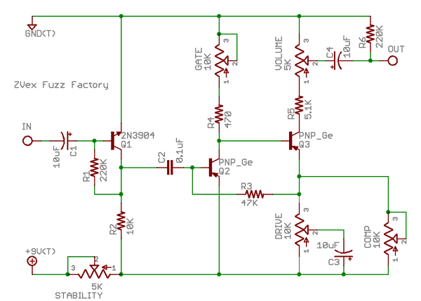
Keep in mind that there have been a few versions of the Fuzz Factory over the years. The only changes have been some of the component values.
Here’s the schematic for the Berserker Fuzz pedal:
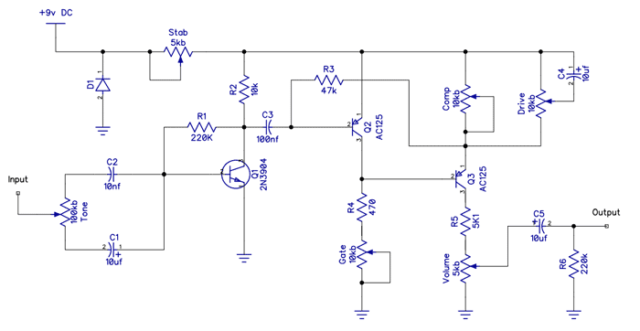
If you compare the schematics, you can see how closely the Berserker Fuzz is based on the Fuzz Factory.
If you’re interested in learning about pedal clones and modifications, check out my tutorial on building a Klon Centaur clone from a kit. The Klon Centaur is one of the most heavily cloned and modified pedals and you may be surprised by how many big-name pedals are basically Klon clones.
Drilling the Pedal Enclosure
The first step to building a guitar pedal is to drill and prepare the pedal enclosure.
For this build, I’m using a 1590B enclosure. The 1590B is a standard-sized pedal enclosure and fits this effect.
Although as you will see on the completed pedal, there isn’t much room between the knobs and the footswitch.
So you may prefer using a larger pedal enclosure to give yourself space to work as well as more space for your foot to hit the footswitch without hitting the knobs. A 1590BB enclosure would be perfect if you want more space.
There are two reasons why I recommend drilling and preparing the pedal enclosure before you start wiring up the effect.
The first reason is if you want to paint the pedal, doing this first will give it more time to dry and cure. Once you wire up and mount your guitar pedal, the chances are slim that you’ll unmount everything just to paint your pedal.
I’ve seen countless DIY guitar pedals in bare metal enclosures because people don’t want to undo a lot of hard work just to paint the pedal. So I highly recommend painting or designing your pedal enclosure before you build your effect.
The other reason I recommend drilling your pedal enclosure first will be clear later on when I mount the pedal.
This kit included a drilling template as shown below:
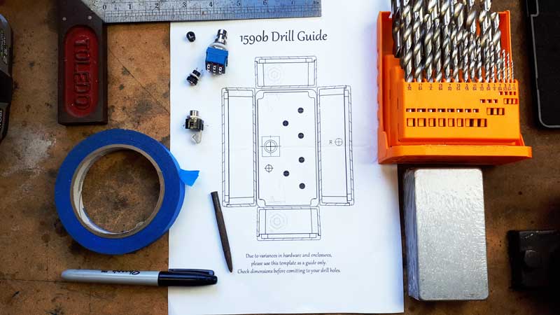
The only time I recommend using a drilling template is when the potentiometers are mounted to the PCB. In those pedals, you want an accurate template to make sure that everything lines up with the PCB.
If the potentiometers are not mounted directly to the PCB, I suggest doing your own measurements. I don’t recommend relying on drilling templates found online as you can get better results with manual measurements.
Here are some reasons why I don’t recommend relying on guitar pedal drilling templates:
- Most templates don’t include measurements, so there’s no way to double-check anything
- Accidentally printing at the wrong scale will throw off a template (many printers don’t print at a perfect 100% scale)
- There can be small variances in pedal enclosure sizes from different manufacturers, which can throw off your template
- Some templates are inaccurate
- If the template slips of slightly moves during drilling, you won’t notice it until it’s too late
- Templates can sometimes hide slipped or off-centered drilling
For example, the template for the Berserker Fuzz pedal is slightly off with the spacing between the potentiometers compared to the spacing on the PCB. It was only slightly out, but it was enough to create some headaches for me when I went to mount the PCB.
To avoid the problems I had, I should have drilled the holes for the potentiometers slightly larger than I did. I only drilled them large enough for the pots to just fit, so they had no wiggle room. Drilling your holes slightly larger gives you some room for error.
If you accidentally drill a hole off-center, a slightly larger hole compensates for that inaccuracy. So try to drill the holes with a little bit of room for the part to move around, but not so big that the nut and washer don’t sit properly.
If you use a template, print it off, cut it out, and securely tape it to your pedal as shown below:
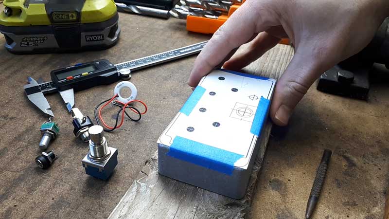
As I mentioned, you don’t want the template to slip during drilling and throw everything off. So make sure it is secured tightly on the pedal enclosure.
Use a center punch tool to mark the center of each hole you want to drill.
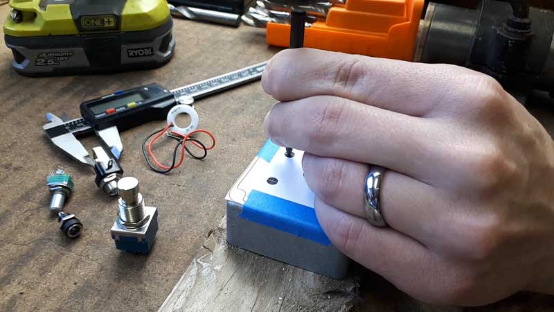
Firmly punching the center of each hole prevents the drill bit from slipping. Even if you use a bench drill press, I highly recommend using a punch tool to dent the center of each position.
The easiest way to drill a guitar pedal enclosure is with a step drill bit (link to a set on Amazon) on a bench drill press.
If you don’t have either, a standard set of drill bits and a handheld drill is perfectly fine to use.
Start with a small drill bit and gradually work your way up to full size as shown below:
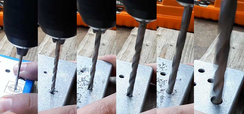
Guitar pedal enclosures are made from aluminum, which is soft and easy to work with. Take your time and don’t force the drill bit. Hold the pedal firmly or clamp it down to prevent it from sliding.
If you use a drill press, be aware that most pedals aren’t perfectly square. So while you may be able to easily drill the face of the pedal, you may notice it becomes awkward on the sides.
Here’s the end result:
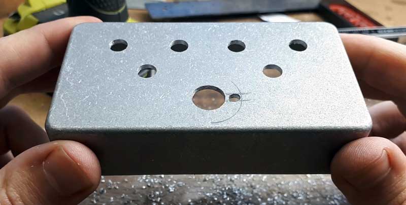
If you’re wondering what the small hole is to the right of the footswitch hole, that’s for the LED ring I used for this build.
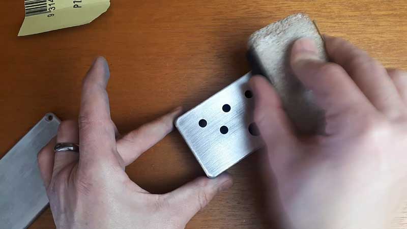
Use a round file or sandpaper to remove any burrs on the inside edge of the holes.
Preparing the Pedal Enclosure
The next step is to prepare your pedal enclosure for painting or however you want to display it. In this build, I hydro dipped the enclosure to get a swirl pattern.
I cover hydro dipping in this guide if you want to see this process in detail.
If you want to paint your pedal enclosure, start by sanding the pedal smooth. Start with 180 grit sandpaper or higher, then work your way up until you’re happy with the results.
After sanding this enclosure up to 360 grit sandpaper, I applied a base coat and let it dry overnight before dipping it.
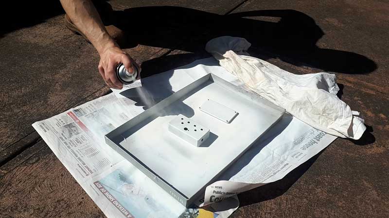
If you plan on spray painting your guitar pedal, doing this step before you wire up the pedal will give the paint time to cure.
Here’s a look at hydro dipping this pedal:
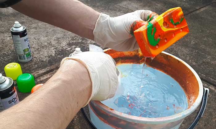
I have full step-by-step details of hydro dipping in this guide if you want to learn more.
Populating the PCB
Once your guitar pedal enclosure has been painted or designed, you can move on to building the effect.
If you buy any guitar pedal kit, you should get a nicely labeled PCB similar to this one:
The Berserker Fuzz pedal kit has all of the components clearly labeled on the PCB. This makes it easy to find where each component needs to go.
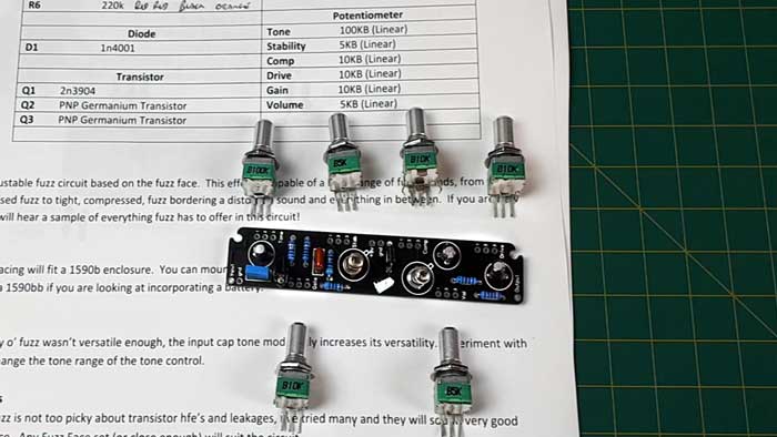
Sort out your kit’s components and make sure everything is correct.
As this is a basic circuit, I matched up each component with the schematic as shown below:
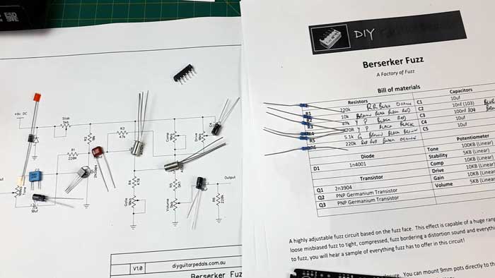
If you have a more complicated pedal you’re building, you may need to come up with another way to sort through the components. You can see that I arrange the resistors on the list. Doing this makes the next step easier.
The best practice with populating a PCB is to start with the lowest height components, then work your way to the tallest components.
This usually means starting with resistors and diodes.
Resistors
You can either solder one component in at a time, or do all of the same type at once. As there are only a few resistors, I soldered all of them at the same time.
Resistors are usually labeled with an ‘R’ and a number on the PCB. In the below photo, you can see that I’m adding a resistor to the R3 position.
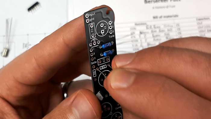
You want to bend the ends of the wire to neatly fit into each position. Insert the resistors into the PCB from the top side (with the printed labels as shown above). Resistors don’t have polarity, which means it doesn’t matter which direction they point. The colored lined don’t need to line up in a particular direction.
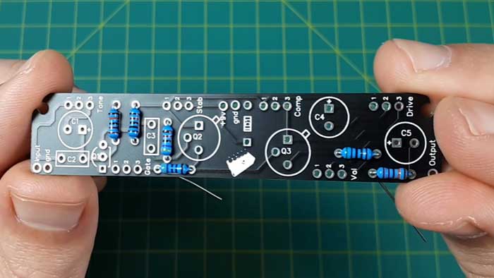
Here are all of the resistors added to the PCB ready to solder:
When soldering, try to avoid holding the soldering iron on the PCB for too long. You don’t want to overheat any components and risk damaging anything.
Hold the tip of the soldering iron on one side of the component’s wire, then press the solder wire to the other side. Try to avoid touching the solder directly on the soldering iron as you want the solder to melt onto the component and not the iron.
If you’re new to soldering, you might want to practice on scraps before you do this on your guitar pedal. It won’t take long to get the basic hang of soldering.
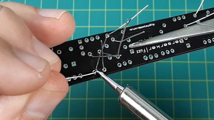
Here’s what your solder joints should look like:
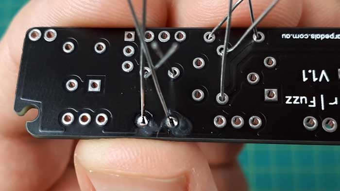
Notice that the joints are shiny and completely cover the hole.
If your solder doesn’t look like this or isn’t shiny, touch the soldering iron on the joint to reflow it. A ‘cold’ solder joint can cause connection problems, so avoid headaches later on by making sure every solder joint looks good before moving on.
After you’re happy with your solder joints, cut the ends of the wire.
Diodes
After soldering all of the resistors, diodes are next.
The key point to remember with diodes is that they must be mounted the correct way. If you mount a diode the wrong way, your pedal won’t work.
Diodes have a line on one side and the PCB should also have a line to let you know which way they need to go. You can clearly see that the diode symbol for D1 has a line on the left side. The grey line you see on the diode needs to match this.
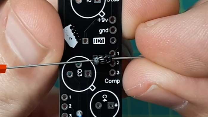
Silicon and germanium diodes may look different, but they both will have a line on one side to let you know which way they need to be installed.
Capacitors
Some capacitors can be mounted either way, while others must be installed in a specific orientation.
The blue capacitor I’m installing below (and the reddish-brown capacitor to the right of my thumb) can be installed either way and will work fine.
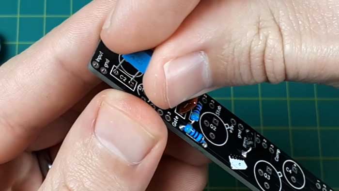
If the PCB doesn’t have anything to indicate polarity, it probably means you can install them either way. But double check your build docs or schematic before installing anything. Search for your capacitor if you’re unsure whether it’s polarized or not.
Electrolytic capacitors are polarized and must be installed in the correct way.
There are a couple of clear signs that these capacitors are polarized:
- One leg is longer than the other (the longer leg is positive)
- There is a negative symbol on the side of the capacitor along with a bright stripe
- The PCB has a positive symbol to indicate which way to install the capacitor
In the below photo, you can clearly see that the C4 and C5 capacitor positions on the PCB are polarized.
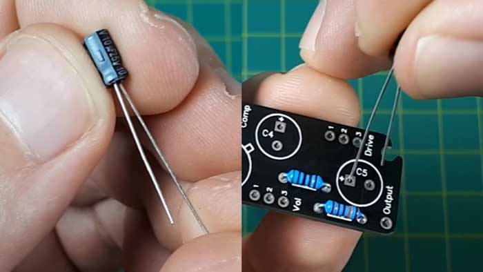
The longer leg is positive, so I install it in that direction.
Transistors
The Berserker fuzz pedal uses two types of transistors: silicon and germanium.
Germanium transistors are common in fuzz pedals and this pedal uses AC125 germanium transistors.
You can see in the below photos that the PCB makes it clear which way to install the transistors. Transistors must be installed the correct way or else they won’t work.
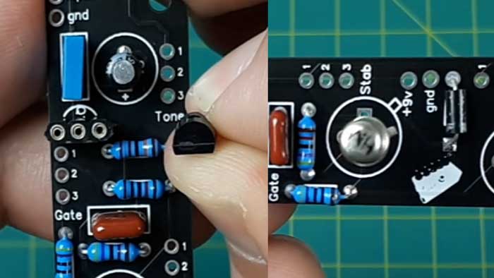
Some kits will include a socket to install transistors as shown above left. Sockets avoid the issue of accidentally heating a transistor too much during soldering because you only need to solder the socket.
Sockets are also used on IC (integrated circuit) chips.
Here’s the end result of soldering all of the components to the PCB:
You can see why I recommend this kit as a good starting point for anybody wanting to get into building guitar pedals. There aren’t many components and you get to learn about a few different types of capacitors and transistors.
There are simpler pedals you can build if this looks intimidating, but it’s not as bad as you might think.
Potentiometers
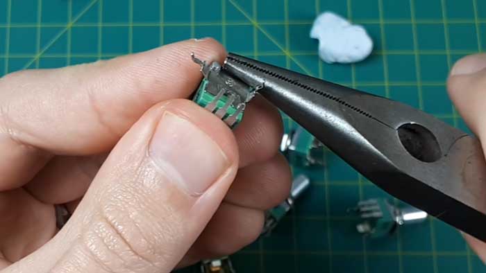
Potentiometers are what the knobs on a pedal are connected to. There are six pots on this pedal and the correct pots must be used in the correct positions for the pedal to work properly.
These alpha pots have little legs meant for mounting, but for this kit, they get in the way. I bent and remove these extra mounting legs while taking care not to damage the base or the other three legs.
I also applied some tape to the bottom of the pots to prevent them from shorting out anything on the PCB. I highly recommend using some double-sided tape on the back of any pots that are mounted to a PCB.
This is why I recommend drilling and preparing your guitar pedal enclosure before working on the circuit.
If you were to solder the pots to the PCB now, you may find that they don’t perfectly line up with the drilled holes. Trying to force them into position can damage your solder joints or PCB.
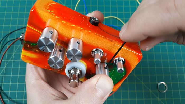
In the below photo, you can see that I pushed the pots through the holes before soldering them.
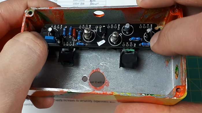
This was really important for this build because I found out after drilling that the template was slightly inaccurate. So mounting the pots before soldering allowed me to bend their legs slightly so they would sit properly.
I highly recommend soldering your potentiometers with the PCB mounted in the enclosure. This won’t be possible with all builds, but it’s worth doing if you can.
Testing the Circuit
Once all of the components have been soldered to the PCB, you will be tempted to install everything in the enclosure and finish your pedal.
Don’t do it.
I know it’s tempting, but I strongly recommend testing your circuit before you install it in the pedal enclosure.
Testing it now will save a lot of headaches later on.
Think about it this way – if you mount everything in the pedal enclosure and the pedal doesn’t work, it could be an issue with so many different things. It could be the input/output jacks, the power supply wiring, the footswitch wiring, the LED wiring, grounding issues, etc.
On the other hand, if you test your circuit out before installing it in the pedal enclosure, any issues can only be due to what has been soldered to the PCB. In other words, you will be able to track down the problem faster.
I’m following this simple testing diagram that was included in the Berserker Fuzz build docs (available on the DIY Guitar Pedals site).
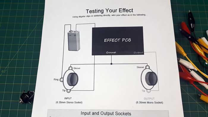
The basic idea is that you wire your PCB up to a battery and connect it to your guitar and amp cables. If the circuit works fine, you can then move on to adding the footswitch and mounting the pedal.
If it doesn’t work properly during testing, it makes it much easier to diagnose the problem.
I recommend buying a set of alligator clips as they make testing your guitar pedal a breeze.
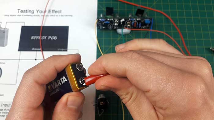
Simply clip the wires to the battery and input/output jacks, then plug your guitar and amp in.
Keep in mind that there is no footswitch during testing, so start with the volume knob all the way down to prevent blowing your ears or amp.
If your effect works properly, you can move on to mounting and assembling the pedal.
Assembling the Pedal
Mount all of the components, but don’t tighten the nuts until you know everything is in position properly. Depending on the space in your enclosure, it can be tricky to fit everything in.
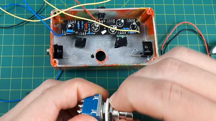
The Berserker fuzz runs off of external power as you can see there isn’t room to store a 9V battery.
Once all of the components are in position, tighten everything just enough to keep everything in place.
I couldn’t help myself and added the knobs at this point, but I recommend doing this only after you wire everything up and you know everything works.
Wiring your guitar pedal up at this stage is called ‘off-board wiring’. There are a few different diagrams available online you can follow depending on how you want your pedal wired up.
Guitar pedals can be wired up in a number of different ways depending if the pedal uses a buffered bypass or True Bypass (explained in this guide). The wiring also changes if you want to use a battery or you’re only using external power.
Here’s what my pedal looked like after wiring everything up.
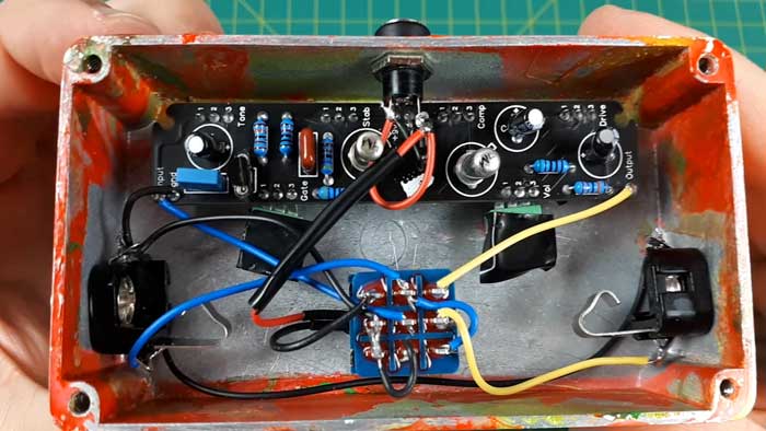
The black tape over the red cable protects a current limiting resistor for the LED. The LED ring was too bright and I wasn’t sure if it included resistors in the ring, so I added a resistor to dim the brightness and prevent the LED from burning out.
If you want to use a LED that isn’t already included as part of the PCB, make sure you add a resistor to prevent it from burning out.
I’m working on a set of off-board wiring diagrams for a future guide, so subscribe to email updates here to stay up to date.
Completed Fuzz Factory Pedal
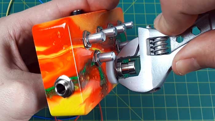
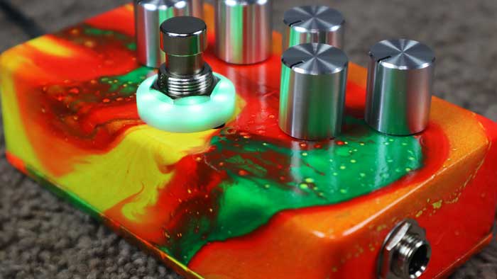
After wiring everything up and mounting the components, here is the completed pedal:
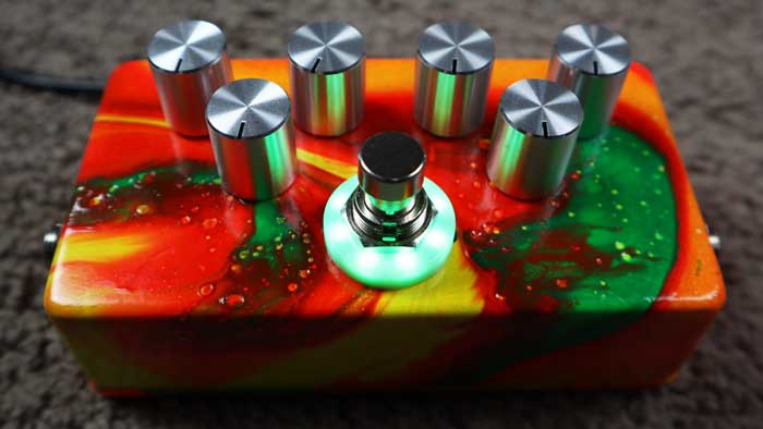
The green LED ring looks fantastic in person and much better than what you see in the above photo.
The polished knobs work well with the bright swirling paint job. The knobs are close together, but it’s not too difficult to tweak the settings – which is something you’ll do a lot if you build a Fuzz Factory clone.
If you are interested in building your own version of this pedal, check out the Berserker Fuzz kit here. If you do buy the kit from outside of Australia, I suggest buying a 1590B pedal enclosure separately in your country to cut down on postage costs.
DIY Berserker Fuzz Pedal Kit Review
Overall, I’m extremely impressed with the Berserker Fuzz kit.
It’s a simple circuit with only a handful of components, so it’s a great kit to learn the basics of building guitar pedals. There are simpler pedals you could build if you’re just getting into DIY pedals, but I feel this one would suit most beginners.
The PCB is well designed with plenty of space between components. At no point did I feel worried that I would mess up the soldering and accidentally bridge connections.
The build docs provided enough information for me to build this pedal without major problems and the questions I sent to Paul were promptly answered with helpful responses.
The pedal performs exactly as I have heard in videos demonstrating the Fuzz Factory and produce all the wild oscillating sounds you would expect.
Check out the range of guitar pedal kits on the DIY Guitar Pedals site here.
Hear the Berserker Fuzz Pedal in Action
I’m currently editing a video walking through this entire build process from start to finish as well as demonstrating the various fuzz sounds it produces.
Subscribe to my YouTube channel here to get notified when the video is up.
I’m currently working on a lot more guides and videos on building guitar pedals, so subscribe to email updates here to find out about these guides.
Check out my Ultimate Guide to Building Guitar Pedals to learn about the tools, hardware, kits, and steps involved in building any guitar pedal.
Learn more about fuzz in my Ultimate Guide to Fuzz. The guide covers popular fuzz pedals including the Fuzz Factory.
If you really want to learn the difference between fuzz, distortion, overdrive, and other effects, check out my Guitar Effects Course. It covers all types of effects in detail.
If you do build a fuzz pedal, check out these Songs using Fuzz for some riffs and songs to learn.