
In this guide, I’ll explain how to build one of those cheap Klon Centaur clone kits you can find all over Amazon, eBay, AliExpress, DHgate, and similar sellers.
If you’re interested in getting into building guitar pedals, I suggest building a simpler kit before tackling a Klon clone.
Check out my Ultimate Guide to Building Guitar Pedals for everything you would want to know about DIY guitar pedals including recommended tools.
Note: even if you don’t want to build this exact pedal, this guide gives you a great overview of the steps to go through when building a guitar pedal. I explain the components and best practices in detail, so read through this guide to learn more about building any guitar pedal.
If you want to learn why the Klon Centaur is such a popular pedal to clone, check out my Guide on the Klon Centaur. The guide explains the hype behind this pedal, schematics, and more.
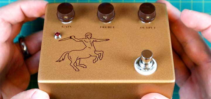
Klon Centaur Clone Kit
I order my Klon clone kit from Aliexpress, but it is identical to this Klon kit (link to Amazon). I assume all of these kits come from the same manufacturer in China and sold under different seller accounts.
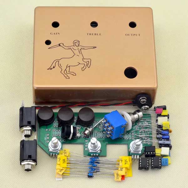
If you buy anything that resembles the above kit, you will be able to follow this guide to build your pedal.
Once your kit arrives, start by making sure there’s no damage to anything, then sort out all the different components.
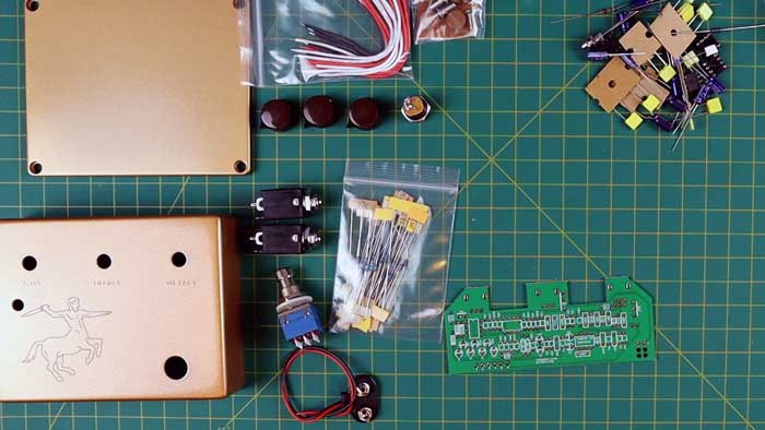
If you’re new to building guitar pedals, I’ll explain the different components throughout this guide.
The only instructions that will arrive with your kit is a one-page list of basic tips and a black-and-white diagram as shown below:

This diagram has confused a lot of people. Who thought it would be a good idea to use a black-and-white diagram without any labels to explain where to wire everything?
I created this guide partly to help anybody who is confused about the included diagram. I have created clear diagrams in color throughout this guide to help you if you build this pedal.
Step 1: Resistors
The general best practice with building guitar pedals is to start with the lowest height components, then work your way to the taller components.
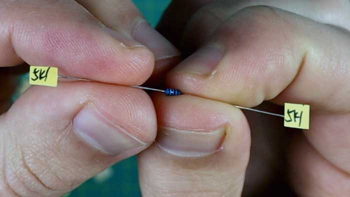
Let’s start with the resistors, which are the blue components with colored-lines. These colored lined are codes for the value of the resistor. You can easily look up any resistor color chart if you want to double-check a resistor’s value.
Sorting Out Resistors
Start by sorting out all of your resistors. Line them all up on your table from lowest to highest value. This makes it easier to find them as you populate your PCB.
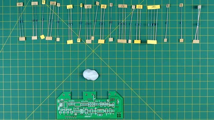
If your kit is like mine, the resistor values will be labeled as shown below:
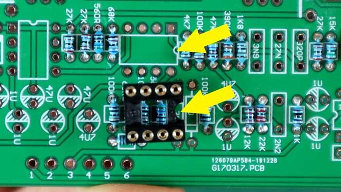
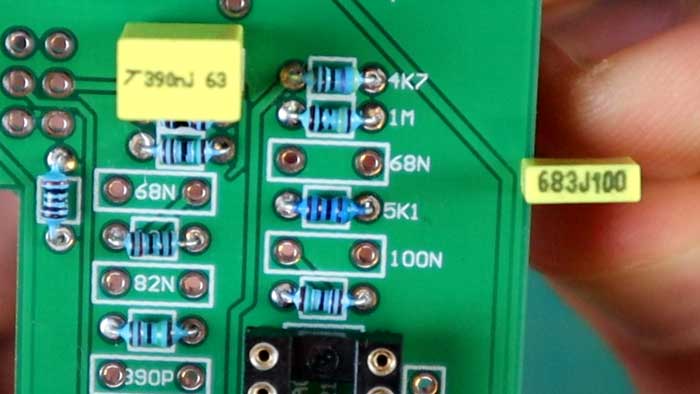
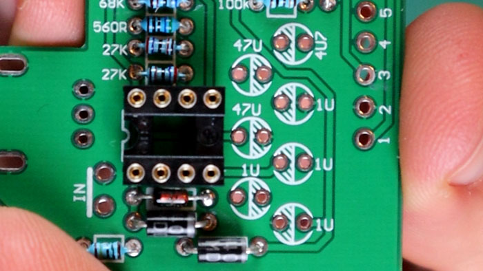
The resistors will be labeled with numbers and either a R, K, or M. Resistors are labelled on the PCB with a small box in between two holes.
Take a look at the PCB for these letters and the small boxes to identify resistor components:
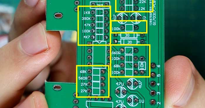
I have highlighted the resistors in this section in the yellow boxes.
An important thing to pay attention to is the difference between a resistor like 4K7 and 47K. The 4K7 means 4.7K, so don’t mix these up. You’ll notice this same way of labeling the decimal point with the capacitors (4U7 and 47U shown above on the right circles).
Soldering Resistors
Once you have sorted your resistors out, it’s time to add them to your PCB and solder them.
I soldered my resistors a few at a time by working in blocks. You can either solder one at a time, working in blocks of a few at a time, or position all of them at once and solder all of them in one hit.
I suggest starting with one at a time if this is your first pedal build.
Match up a resistor then bend the wires so it rests nicely against the PCB as shown below:

Note: it doesn’t matter which way the resistors go. Other components need to be orientated in the correct direction, but you don’t need to worry about that with resistors.
You can slightly bend the wires at the back to hold the resistor in position. This is handy if you want to solder a few components at once. You definitely don’t want them to all fall out before you solder them!
When you solder the resistors, heat up one side of the wire with the soldering iron and add the solder from the other side. Try to avoid touching the solder directly on the iron.

The aim is for the solder to melt from the heat of the component’s wire and not from direct contact with the solder. This takes some practice, but once you can do this, you’ll end up with much better quality solder joints.
Here’s what your solder joints should look like:
Here are the main things you are looking for in a good solder joint:
- Enough solder to completely fill the hole and surround the wire
- Not so much solder that it creates a massive blob (this could create a bridge that shorts out connections)
- A shiny surface – if the surface is dull, it may be a ‘cold’ solder joint. Reflow the solder to fix this
Don’t worry if they don’t look perfect. Soldering is a skill and you’ll get better the more you practice. I still make mistakes and have to redo joints all the time.
Work your way slowly through all the resistors and be careful not to get confused by resistors such as 4K7 and 47K.
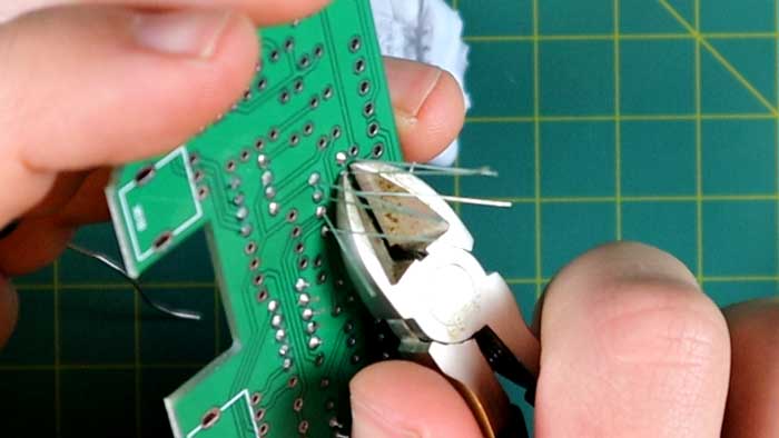
Trim the back of the wires off as you go and try to keep the ends short to avoid possible shorts.
Remember that the resistors are the small boxes, so the larger boxes are for different components.
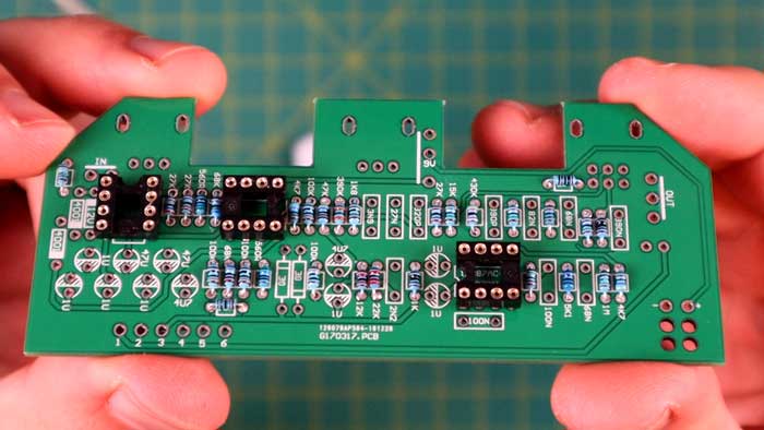
Here’s what your board should look like once you have soldered all of the resistors:

Don’t forget the resistors on the far left, the bottom left, and the top right. It took me a while to find these positions because they don’t line up like the others.
Step 2: Diodes and Sockets
The Klon Centaur uses three chips held onto the PCB using sockets. These sockets ensure you don’t damage the chip by overheating during soldering.
Sockets and Chips
The important point to remember with the sockets and chips is that they have a semicircle cutout to help you identify which way to install them.
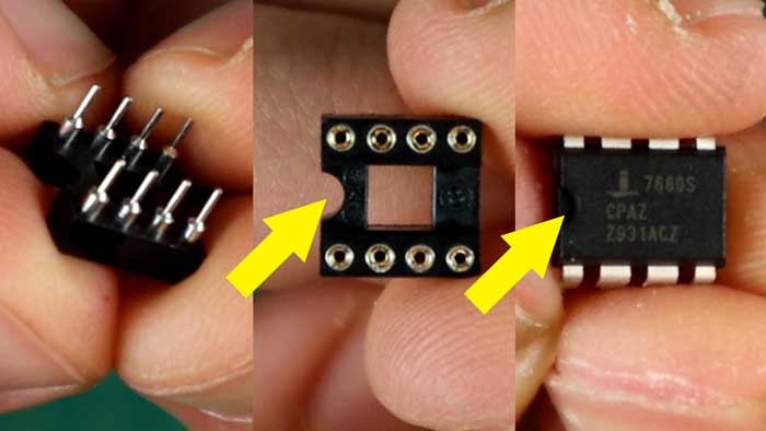
Notice that in the above photo, the semicircle on the chip matches the semicircle on the socket. Two of the chips in the kit will have a circle towards one end of the chip instead of a semicircle.
On the PCB, you’ll see this same semicircle to show which way to install the sockets.
While it doesn’t really matter which way you install the sockets (don’t panic if you put them in the wrong way), it does help you line up the chips properly. Make sure the chip direction matches the direction shown on the PCB or your pedal won’t work.
Make sure the socket is resting fully against the PCB as you solder it in to avoid it sitting crooked.
Here’s what your sockets should look like after you solder them in:
I recommend installing the chips later on after everything else is installed, but I’ll explain installing them now.
There are three op-amp chips to install. Two TL072 chips (with a circle to show direction) and one 7660 chip (with a semicircle cutout).
The 7660 chip is installed on the far left position (aligned vertically). The other two chips go in the middle and right positions.

Notice the circles on the two TL072 chips. Make sure those circles are closest to the notch in the socket.
Push the chips in all the way but be careful not to bend any of the pins.
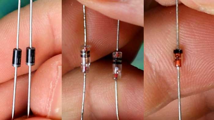
Diodes
There are three different diodes used in the Klon kit, which can cause some confusion. The page of ‘instructions’ that comes with the kit only says that the odd one out goes right next to the left socket.
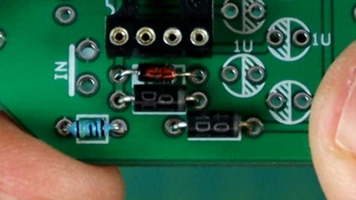
The odd one out is the one on the far right in the below photo. This diode is installed in the position labeled ’12V’.
The important thing to remember with diodes is that they must be installed in the correct direction. All diodes have a line (or two lines) on one end that must align with the instructions on the PCB.
In the below photo, you can see that I have lined up the black line with the line on the PCB.

The two diodes labeled 4001 below the 12V diode are the silver and black diodes (silicon). Line the silver lines up to the right as shown in the above PCB.
The last two diodes are installed in the positions labeled ‘GE’ for germanium. Align the double lines as shown below:

Once you have correctly soldered in the diodes, you can move on to the last components that need to be installed.
Step 3: Capacitors
There are two main types of capacitors to install in your Klon kit – electrolytic and polyester box capacitors. There will likely be a couple of odd-looking capacitors if your kit is like mine, so I’ll go through them.
Yellow Box
Start with the yellow box capacitors. These are labeled on the PCB with the large rectangles and a number such as 390N or 68N.

Some of the numbers will match up perfectly like the above 390N, while others may slightly vary.
For example, the 68N reads as 683J100 on the box as shown below:
If you’re ever unsure, simply Google the code on the capacitor to find out what the value is.
The yellow box capacitors can be installed in either direction.
Be careful not to heat the component legs too long or it may damage the capacitor. Even the page of instructions recommends sitting the capacitor slightly higher on the PCB to avoid heating it too much.
My kit had two capacitors that don’t match the rest of the yellow boxes. I have seen other kits with capacitors that looked different from these two, so yours may vary.
Once you have installed all the yellow box capacitors, you may or may not end up with two that look like these:
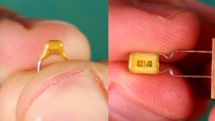
The 391 ceramic capacitor is for the position labeled 390P on the PCB.
The 821JQ capacitor is for the position labeled 820P. The ‘8’ on the PCB is cut off, so it may look like 320P.
Don’t worry if your capacitors look different than these. Google the codes if they differ from these to double-check that you have the correct values.
Here are all the yellow capacitors installed so you can double-check the codes and positions:
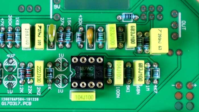
While it doesn’t matter which way you install these capacitors, it helps if you install them all in the same direction so you can easily read the codes.
Electrolytic
Electrolytic capacitors are the bigger cylindrical components and they can come in a few different colors. Mine were dark blue, but don’t worry if yours differ.
Electrolytic capacitors must be installed in the correct orientation or your pedal won’t work.
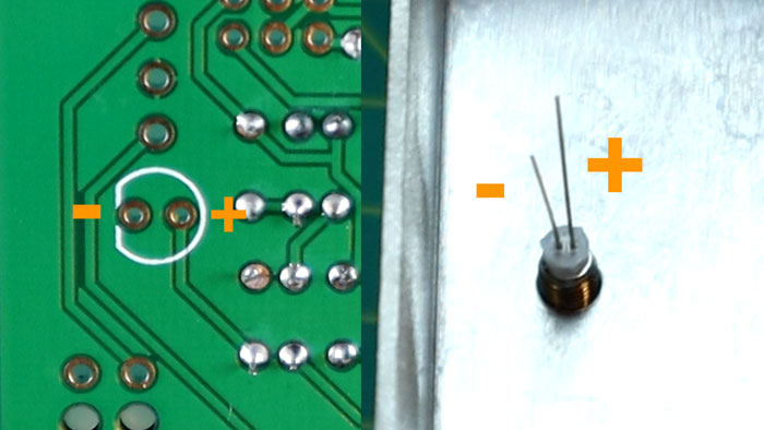
There are two ways to read the orientation of an electrolytic capacitor:
- One side of the capacitor will have a thick line running down with a negative symbol (-)
- The longer leg is positive (+)
The below diagram shows what to look for:
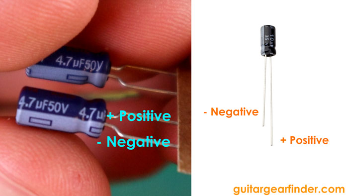
While some electrolytic capacitors may look different, they all follow these two ways of identifying which side is positive and which side is negative.
The value of the capacitor will also be written on the side. The above-left capacitor shows as 4.7µF. On the PCB, 4.7 is shown as 4U7 (this is similar to how resistors with decimal points are displayed).
On your PCB, the electrolytic capacitors are the circles and should be the only positions without components at this point:
Notice the 4U7 capacitor on the top right. This is for the 4.7µF capacitor. Don’t mix up the 4.7µF and the 47µF capacitors!
The side of the circle with the striped lines is the negative side. This means the long leg is inserted into the blank side of the circle as shown below:
You’ll find after installing a couple of these that there’s not much room between each one. They quickly become cramped and press against each other (which is okay).
It’s up to you whether you want to solder one at a time or multiple capacitors at once. I suggest soldering two at a time to make sure they sit snug against each other.
Once you have installed all of these capacitors, you have completely populated the PCB. Insert the op-amp chips if you haven’t already done so and your board should look like this:
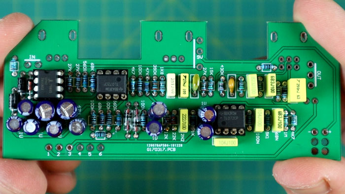
Great job if you got this far! If this was your first pedal build, I’m sure it seemed overwhelming when you saw the pile of components. It feels good to get to this stage, but there’s still some work to go, so don’t try to rush through the next steps. Take your time and you’ll end up with a great-sounding pedal.
Do a visual inspection of all of the components to make sure there are no obvious mistakes such as a chip installed the wrong way.
Also, check over the back of your PCB and make sure all of the solder joints look good.

All of the solder joints should look shiny, completely fill the hole, and surround the component’s wire.
If any of the solder joints look suspicious or dull, use the soldering iron to melt the solder or add more if needed.
There should be no connections between these solder points and if you see any grime or flux in between two joints, use a sharp knife or tool to lightly scratch the surface clean.
A near-invisible solder bridge can be enough to prevent your pedal from working, so look ever every joint closely.
Taking a few minutes to carefully go over all of your solder joints now can save you hours of headaches later on.
Step 4: Mounting Pedal Hardware
Now it’s time to mount some of the parts into the pedal enclosure. I feel it’s important to do this before you solder the potentiometers onto the PCB.
LED
Start by installing the mounted LED. Remove the screw and insert the LED into the correct position.
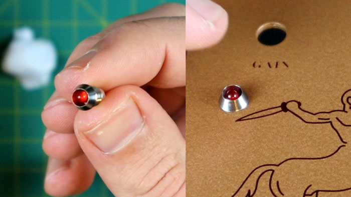
Add the screw back onto the LED but don’t completely tighten it until the LED is orientated the correct way.
The LED needs to be soldered onto the PCB, so we need to make sure it lines up with the correct holes.
On the back of the PCB, you’ll see a symbol for the LED as shown below:
The flat side of the LED symbol is negative, which matches the short leg of the LED.
Line up the LED so the short leg (negative) points towards the edge of the enclosure. Tighten the nut once the legs are lined up as shown in the above photo.
Power Jack
Remove the power jack’s nut and insert it into the enclosure as shown below.

Tighten the nut once you’re happy with how it lines up. I suggest keeping it the same as you see above so you can follow along with my wiring instructions.
Footswitch
Install the footswitch and line it up so the inside lugs match the below photo:
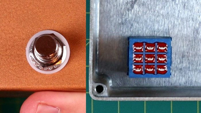
It’s important that the footswitch lines up this way or you may have issues with wiring. The holes in the nine connection points should be pointing up and down, not side to side.
Input and Output Jacks
While it doesn’t really matter which way these line up, I suggest making sure both of them are orientated the same way to make wiring easier.
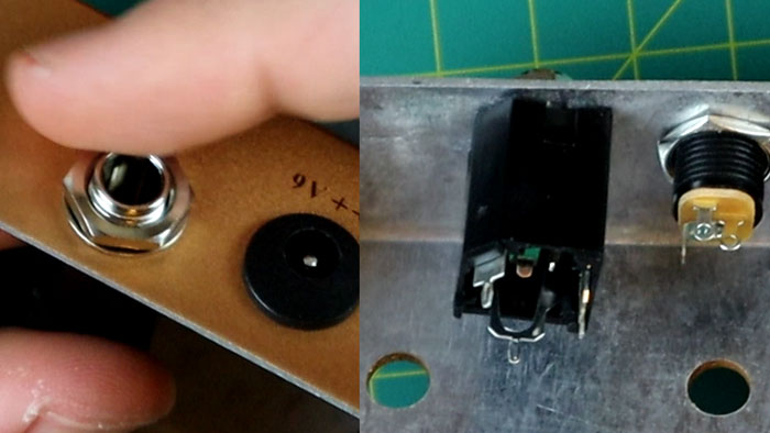
I lined mine up with the angled side on pointing to the top left. If you line yours up like the above photo, you’ll find it easier to follow my wiring diagrams.
Once you have all of these parts mounted, your pedal enclosure should look like this:

Now it’s time to wire up the PCB and get ready to mount it.
Step 5: Wiring
Wiring is the most confusing part of building this kit due to the ridiculous black-and-white photo the kit comes with.
If you follow this guide, you won’t have to worry about the issues that I’ve seen other people experience due to wrong wiring.
My kit came with three colored wires: red, black, and white. Other kits only had one color for all of the wires. Regardless of the colors of your wires, pay extra attention to how you wire up your pedal.
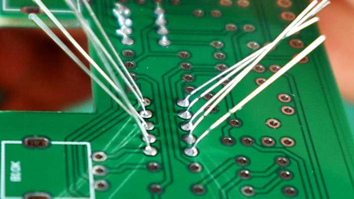
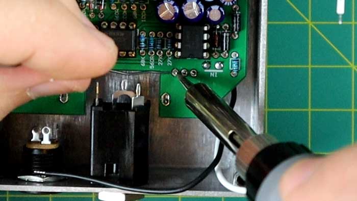
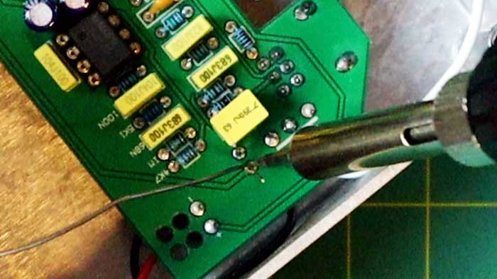
Add Wires to PCB
The first step is to add wires to all of the points on the PCB.
There are 14 points you need to add wire to your PCB (and another two for the battery clip).

The top left is for the input jack, bottom left for the footswitch, middle for power, and right for the output jack.
I added wires to the underside of the PCB, but if I were to build this pedal again, I would wire them from the top so I could easily see the connections. It’s up to you which side you add the wire to the PCB.

The black and white photo was useless in trying to figure out what color wires to use, so I just made sure each wire was a different color for each section.
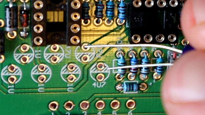
Here’s my wired PCB with the battery clip wired up on the bottom right:
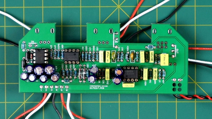
If you intend to use a battery, those four spare holes are to thread the battery wires through. This helps protect the solder joint if you accidentally pull the wires when adding or removing a battery. As I don’t intend to use a battery, I wasn’t thinking about this and didn’t thread the wires through.
If you wire up your PCB from behind as I did, pay extra attention to the order of the colored wires. For example, the order of the wires for the output jack looks like it goes red, white, and black from top to bottom, right? Well, no it doesn’t. I only found out after my pedal didn’t work on the first attempt that behind the PCB, the white and black wires crossed over. So the order was actually red, black, then white. Don’t worry, I’ll provide clear wiring diagrams so you don’t follow my mistake.
Potentiometers
Once your PCB is completely wired up, it’s time to mount the potentiometers.
Before you mount your potentiometers, there’s a little positioning nub you need to file or grind off. These nubs prevent the potentiometers from sitting flush against the pedal enclosure. So if you don’t file them off, you’ll end up with crooked knobs.
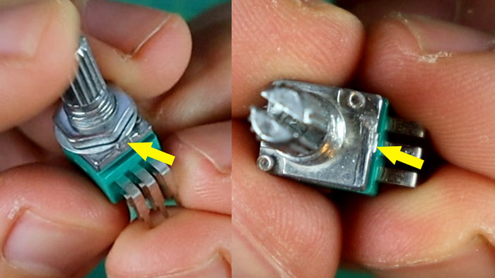
Use a file or grinder to carefully remove the nub. Remove the nut and washer before you try to grind the nub off. You can see on the above right what it should look like after removing the nub.
There are three potentiometers to install and you need to install them in the correct positions.
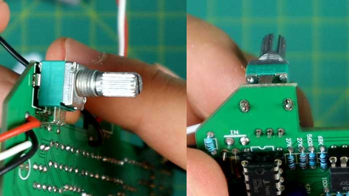
The PCB labels each potentiometer position as shown below:

B104 is the B100K potentiometer (far left), and B103 is the B10K potentiometers.
The easy way to tell these apart is that the B100K potentiometer has six legs, while the other two only have three.
Carefully mount the potentiometers from the underside of the PCB. You may need to use some pliers to gently bend the support legs if needed.
Once these are mounted, don’t solder them yet.
This is a best practice I learned when building guitar pedals. If you were to solder these in now, there’s a slight chance that they don’t perfectly line up with the holes in the pedal enclosure.
Trying to force the potentiometers into the holes after they have been soldered puts stress on the solder joints and the PCB. This is how some people end up with cracked solder joints or damaged PCBs.
To avoid this issue, mount the PCB and poke the potentiometers through the holes.
Note: as you push the potentiometers through the holes, make sure the two legs from the LED go through the two holes on the PCB. This is a little tricky, so start by poking the longer leg through the first hole, then follow with the shorter leg.
Tighten the nut and washer on each potentiometer.
Notice that the potentiometers are perfectly straight in the above photos. This may not have been the case if I soldered them to the PCB beforehand.
Now that the potentiometers are perfectly straight, you can solder them onto the PCB.
Make sure the PCB is pressed right up against the potentiometers before you start soldering.
Solder the main leg points, then also solder the two larger support connections. These points help add stability and prevent any damage to the PCB.
Solder LED
Now that the potentiometers are soldered, you can solder the LED in position. The two wires should be poking through as shown below:
Cut the ends of the LED wires after you solder it to the PCB.
If you ever need to remove the PCB from the enclosure, the LED should slide out from the mounting ring. Be careful that it slides back into position when you mount it again.
Footswitch Wiring
This is where most people who buy the Klon Centaur clone kit get confused. The black-and-white diagram does a terrible job at explaining how to wire up the footswitch.
Here is a clear diagram showing how to wire the Klon’s footswitch:

It doesn’t matter what color wires you use, as long as you correctly match up the positions 1-6 in this order.
Cut the wires to an appropriate length (leave them slightly longer than you think you need just in case you mess up stripping the wire).
Strip the end of the wire using a wire stripper or cutters (covered in the tools section in my Ultimate Guide to DIY Guitar Pedals).
It can be tricky to thread the wire through the holes, so use some needle nose pliers to make the job easier.
Power Jack Wiring
To wire up the power jack, the important point to remember is that there is a leg with a flat section. That leg is wired to the top connection point on the PCB.
Once that wire is in place, use the below diagram to wire the other legs.

The leg opposite the larger leg is the middle connection point on the PCB and the other leg is the bottom connection point.
Input Jack Wiring
The input jack only uses two wires, but the actual jack has three connection points (it’s a stereo jack). Make sure you wire to the correct points or you won’t get any sound out of your pedal.
Tip: you can remove the jacks from the enclosure if you have trouble threading the wires into the correct positions.
The leg with the angled corner connects to the right connection point on the PCB.
The other wire connects to the leg anti-clockwise from the first leg.

The above diagram should make it clear which legs you need to use.
The above photo also shows why connecting the wires to the other side of the board wasn’t the best idea. It can quickly get confusing if you can’t see exactly which wire is connected to each point.
If you ever do something like this, just use a multimeter to double-check the connections before you wire anything up.
Output Jack Wiring
The output jack uses three wires. This is standard for guitar pedals that use a battery (some pedals do this on the input jack instead). When the cable is unplugged, it disconnects the battery so it doesn’t drain.
I made a mistake while wiring this part because I didn’t notice that the wires accidentally crossed over behind the PCB. This photo shows the correct wiring after I resoldered the connections.
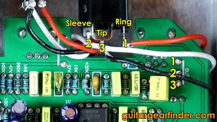
If you get no output signal at all as I did on my first attempt, taking a look at the input or output jack wiring is a good starting point.
Quick Power Test
Before you hook everything up, try a quick power test by connecting the battery and a cable to the output jack (the cable doesn’t need to be plugged in your amp yet).
If both the output cable and battery are connected, the LED should immediately light up or after pressing the footswitch once.
If the LED lights up, congratulations! At least it means power is flowing through your pedal.
Unplug the battery and connect an external power source to the pedal if you have one. If your power jack is wired up properly, you should also see the LED light up.
If these quick power tests work, you can move on to testing your pedal out.
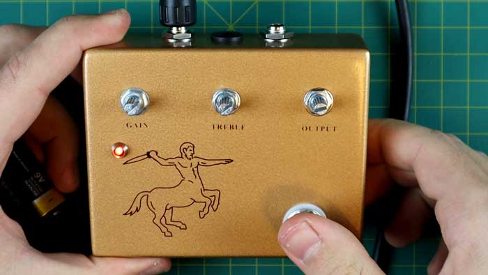
Final Touches
If you test out your pedal and everything works, congratulations!
It’s rare for a DIY pedal to work perfectly on the very first attempt, so well done if you actually get a signal and the effect works as it should.
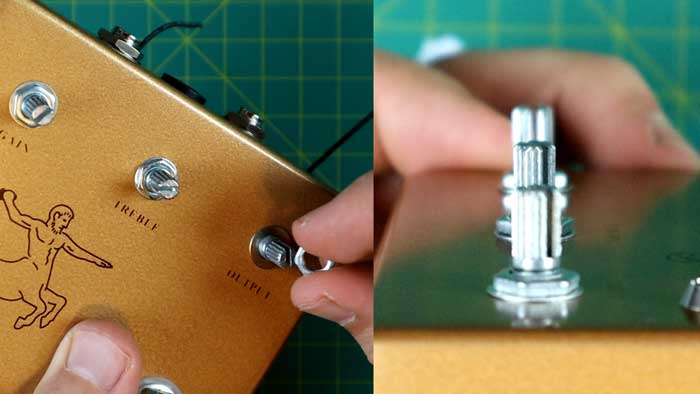
You can finish your pedal off by tightening all of the nuts, attaching the backplate, then add the knobs.

I’ve seen different knobs used in various kits, but mine used a small flathead screwdriver to clamp the knobs in position.
I was pleasantly surprised by how good this kit sounded when used properly. For a cheap clone kit, it is a great pedal to have in your collection.
Find out more about the Klon Centaur in this guide.
It should be clear from the length of this guide that building a clone from a kit takes a lot of work and patience. But if you stick with the instructions in this guide, you’ll get through it.
Troubleshooting Problems With Your Kit
If you followed the instructions in this guide perfectly, you should have avoided a lot of issues other people experienced due to incorrect wiring.
It can be really frustrating to plug in a DIY pedal and it not work properly (or at all). So if your pedal doesn’t work straight away, don’t panic or get frustrated.
You will solve the issues. It will just take some time to locate the problem.
I’m working on detailed troubleshooting guides for building guitar pedals, so in the meantime, I’ll give you some tips and best practices to finding issues with your pedal.
Here is a step-by-step list of what I recommend to try and find problems with your pedal:
- Make sure the cables are plugged in the correct way and your amp and guitar are properly connected with appropriate volume levels (this might seem obvious, but this is often the cause of problems)
- Check the pedal’s power is turned on (or battery connected)
- Look through your pedal’s wiring and compare them to the diagrams in this guide
- Look for any possible shorts or bridges between solder joints
- Check voltage and continuity throughout your circuit using a multimeter
- Build an audio probe and use it to test your entire circuit one component at a time
Almost all of my problems were located using an audio probe, so you could try this earlier if you want.
Here are some things you can check with your multimeter to try and find any problems:
- Voltage level of battery used
- Voltage throughout your circuit
- Continuity between all ground connections
Here are some other tips based on the type of problem you’re having:
- If you get no signal at all, check the wiring on your input and output jacks. The signal isn’t reaching the output jack, so find where the connection fails
- If you’re getting a loud humming sound but no signal (pedal on or off), the wiring on the input/output jack may be reversed (this was the problem I encountered)
Almost all issues in general with building pedals comes down to problems with wiring something incorrectly or bad solder joints. Focus on those areas to identify the problem.
Hear This Pedal In Action
Check out the below video for a look at the entire build process as well as a demo of the pedal:
Subscribe to my YouTube channel or my email list to stay up to date on future videos like this.
Building your own guitar pedals can be a fun hobby once you feel confident soldering and dealing with problems.
Check out my Ultimate Guide to DIY Guitar Pedals for more resources, best practices, and more tutorials like this one.
If you’re looking for a simpler pedal to build, check out this Fuzz Factory clone I built from a kit.
To stay up to date on more tutorials and guides on building guitar pedals, subscribe to my email list here.