
A fuzz pedal is one of the easiest guitar pedals you can build.
In this guide, I’ll show you step-by-step how to build a ridiculously easy guitar pedal using only a few components.
Even if you don’t build this exact pedal, you’ll learn the basic tools, components, and steps involved in building guitar pedals.
Important: If you’re interested in building this pedal or any other pedal, read through my Ultimate Guide to DIY Guitar Pedals first. It explains all the equipment, components, and troubleshooting advice you need to know before you read this tutorial.
7-Minute Fuzz Pedal Kit
The fuzz pedal I’m building in this guide is the 7-minute Fuzz Pedal Kit from DIY Guitar Pedals (they ship worldwide).
If you buy the kit, you can follow this guide for step-by-step instructions.
If you don’t buy the kit, you can still follow this guide for any basic guitar pedal kit such as a boost, fuzz, or overdrive pedal.
Here’s what’s included in the kit:
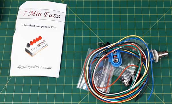
Most DIY kits you buy will come with all of the components you need to build the effect. You normally buy pedal enclosures separately because you can choose between a variety of sizes.
In this tutorial, I’ll be mounting the fuzz pedal circuit in a 1590B enclosure, which is one of the most popular sizes.
Here’s a quick comparison of the most popular pedal enclosure sizes (detailed information in my DIY Guitar Pedals Guide):
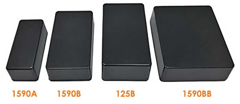
While this circuit is small enough to fit into a 1590A enclosure, its a good idea to start out on larger enclosures if you’re new to building guitar pedals.
It can quickly become cramped in the enclosures, so a larger enclosure will make your job easier.
Populating the PCB
The first thing to do when you buy a DIY kit is to go through and make sure all of the components are there.
I like to lay out all of the components to make it easier when I populate the PCB.
The 7-minute Fuzz kit only uses a few components, so this is easy to do. Here are all of the components for this pedal:
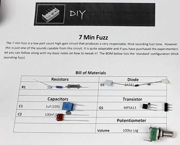
More complicated pedals can have far more components, so this is why I recommend starting out with a simple pedal like this one to get used to the different types of components and how to identify them. I go into detail on how to identify the different components and what they do in my DIY Guitar Pedal guide.
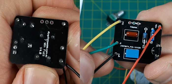
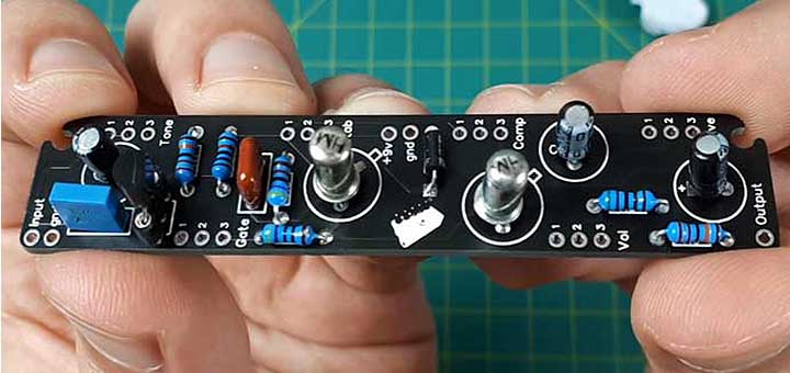
Here is the PCB for this guitar pedal:
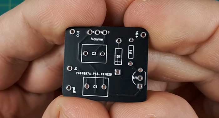
As you can see, the positions for each component has been labeled (eg: C1, C2, D1).
The best practice when building guitar pedals is to start with the lowest height components and work your way to the taller components.
For a simple build like this one it doesn’t really matter which order you populate the components. On more complex pedals, you’ll find that it makes things much easier when you follow this method. See my Klon Centaur clone pedal build tutorial for an example of a more complex build where the order you install the components makes a difference.
The resistors are usually the best starting point, so here’s where the resistor goes:
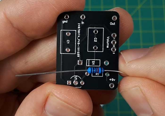
There’s only one resistor in this build, so you don’t need to worry about color codes. Resistors can be inserted in either orientation, so you can’t install it the wrong way.
Carefully bend the resistor legs so you can push the resistor through the holes as shown below:
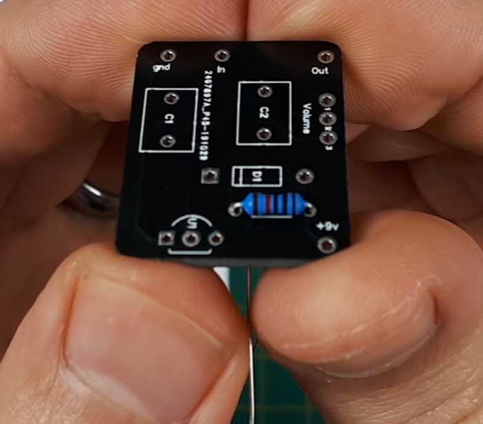
You want to try and have the resistor sit flush against the PCB. It doesn’t matter too much if the resistor doesn’t perfectly push against the PCB, but it helps to keep every tidy as you go.
Before you solder your components, it’s a good idea to find a way to hold your PCB steady. You’ll need two free hands when soldering, so you don’t want to try and juggle the resistor and the PCB at the same time.
I talk about the different options for holding the PCB in place in my DIY guitar pedals guide. I followed the advice shared on the DIY Guitar Pedals YouTube channel (the maker of this kit) and use a blob of Blu Tack. In the US, you might know this as mounting putty or sticky tack.
The big advantage of using Blu Tack is that it will press the component against the PCB in the perfect position while you solder the legs.
You can see in the above photo how the Blu Tack keeps the resistor in position and frees my hands up to solder the legs.
The end result you are hoping to achieve is a smooth and shiny solder as shown below:
Take your time with every solder joint as the most common problem people have with building guitar pedals is bad solder connections.
The next component to solder is the diode. Diodes must be installed in the correct orientation or the pedal won’t work.
As you can see in the below photo, the black line on one end of the diode matches the line on the PCB:
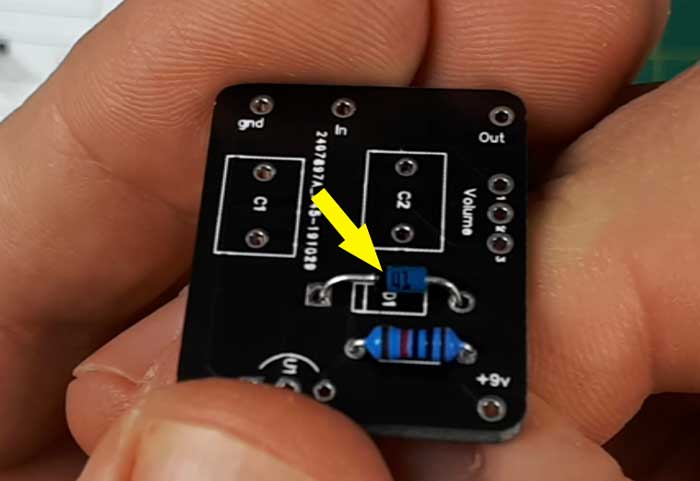
All diodes will use some sort of symbol or line to tell you which way to install them.
This build uses a transistor and the kit includes a mounting socket as shown below:
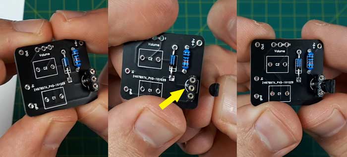
Some kits use mounting sockets for transistors while others don’t. The idea with the mounting socket is that it protects the transistor from overheating while you solder it in position. By soldering a socket to the PCB, you eliminate the possibility of damaging your transistors.
The key point to remember with this type of transistor is that they have a flat side and a curved side. The PCB will make it clear which way to install them as you can see in the above photos.
If you install a transistor the wrong way, your pedal won’t work.
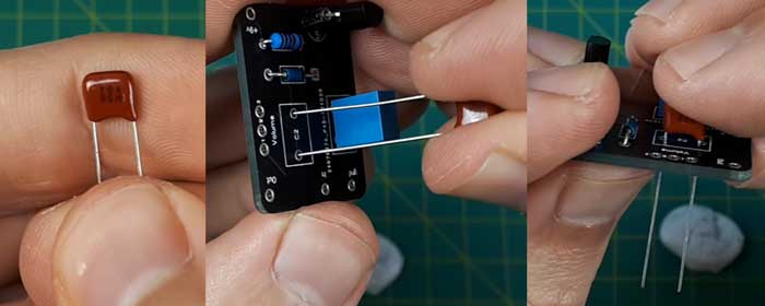
The last two components for this pedal are two capacitors.
The big blue capacitor is installed in the C1 position and the brown transistor in the C2 position. These capacitors can be installed in either orientation.
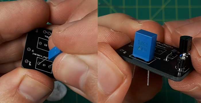
There are a few different types of capacitors and some of them must be installed in a specific orientation (eg: electrolytic capacitors). Read my DIY Guitar Pedals guide for more details.
Once you mount and solder these components, you’re ready to work on wiring.
The ‘7-minute’ name for this kit is based on being able to solder all of these components to the PCB in under 7 minutes.
If this is your first pedal build, it might take you much longer than 7 minutes. Don’t rush – get it right the first time and you’ll avoid serious headaches later on. As you gain experience, you’ll get faster at building pedals.
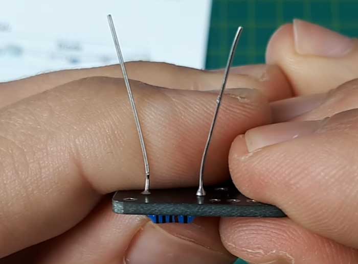
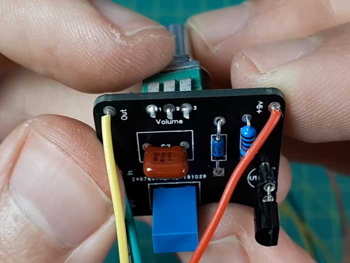
There are four wires to solder to the PCB as shown below:
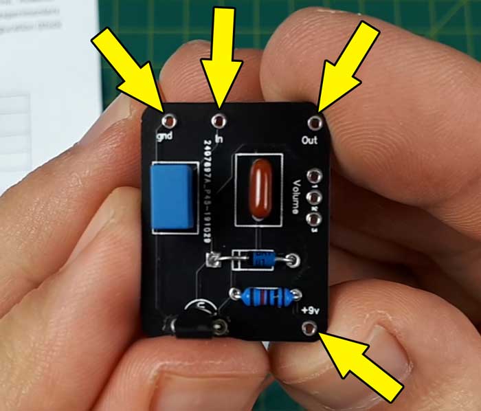
While it doesn’t matter what color wires you use, make sure you can easily tell which color wire is used for different purposes.
Here are the colors I’m using in this build:
- +9V: Red
- GND: Black
- IN: Green
- Out: Yellow
Using red for positive power and black for the ground is the best practice I suggest following. If you only use those colors for those two purposes, you’ll never risk accidentally shorting out your pedal by mixing up positive and negative connections.
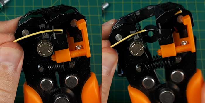
Strip the ends of the wires using a wire stripper. There are a few different types of wire strippers and they all work in similar ways. You can even use wire cutters with a bit of practice.
Once you solder all of the wires in position, this is what you should see:
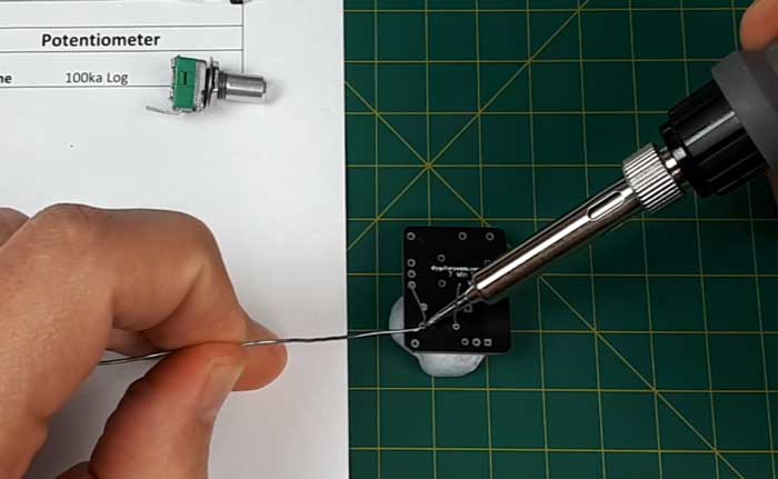
The last component to install is the potentiometer. In this pedal, it will control the volume level of the effect.
Some people like to install the potentiometers before the wires, while others prefer doing it the other way. It’s usually easier to install the wires first as the potentiometers won’t get in the way.
Most potentiometers you buy will have a few mounting legs or nubs on the bottom. Some PCBs have holes to use these mounting legs, while others don’t. If the PCB doesn’t have holes for these extra legs, you can safely cut them off with wire cutters as shown below:
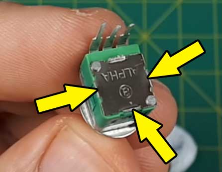
On the other side of the potentiometer, you’ll also see a positioning nub. This is used to hold the potentiometer in position. When using potentiometers in a guitar pedal, we don’t need these nubs. In fact, the nubs make things worse because they cause the potentiometers to stick out crooked from your pedal.
The below-left photo shows the little nub. You can easily file this off and once it is flat (as shown to the right), the potentiometer won’t stick out on an angle from your pedal.
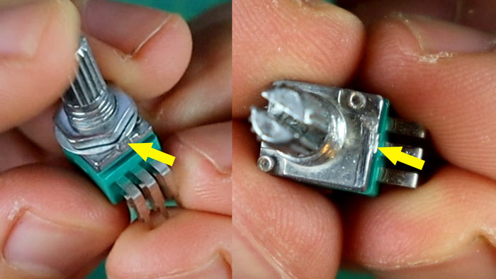
Do this before you mount the potentiometer to the PCB or you might find it gets awkward trying to file it off without damaging your PCB.
The potentiometer is installed on the opposite side of the PCB. To prevent the metal back of the potentiometer from shorting out any other components, use something like tape to cover the base.
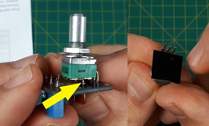
A lot of people experience problems when potentiometers short out components on the PCB, so make sure you do this even if it looks like there is plenty of space between the PCB and the potentiometer. This can quickly change when you mount your pedal.
Here’s what the completed PCB looks like after soldering the potentiometer.
As you can see, this is a ridiculously simple pedal and a great starting point for anybody nervous about soldering and building pedals.
Testing the Circuit
At this point, your pedal is actually ready to use. While you will be tempted to mount it in the pedal enclosure, I strongly suggest testing it first.
As Paul from DIY Guitar Pedals explains, by testing the pedal circuit now, you reduce the chances of experiencing problems later on. If you find your pedal doesn’t work properly now, it’s a lot easier to identify the cause of the problem compared to trying to find out what’s going wrong with everything mounted in a pedal enclosure.
If your circuit works at this stage then doesn’t work when you mount it, it also makes it easier to figure out the cause of the problem. In that case, you’ll know it’s an issue with the ‘offboard wiring’, which is everything you wire up after this stage.
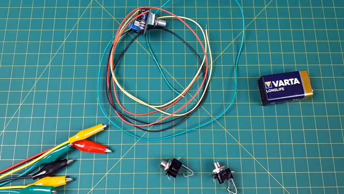
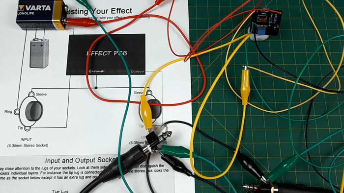
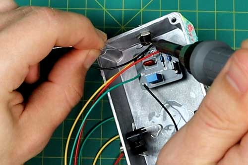
To test your pedal circuit, you’ll need a battery, alligator clips (highly recommended) and your guitar, amp, and cables.
The instructions for the kit includes a diagram on how to test your guitar pedal. You can follow this diagram for most pedals you build. Some pedals will integrate the footswitch and LED into the PCB, which makes it harder to test, but this is a good starting point.
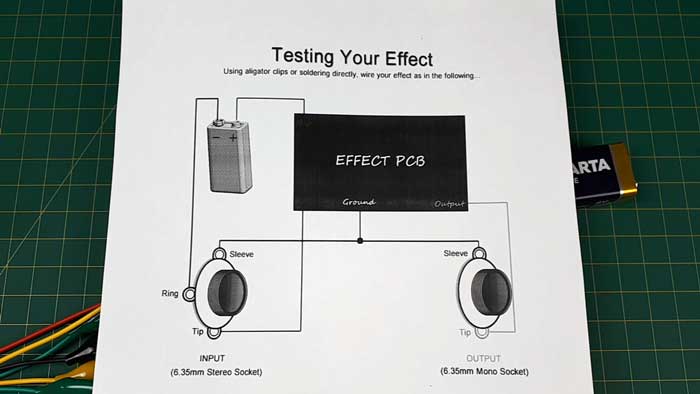
I used the input and output jacks as an easy way to connect the alligator clips to the cables. The below photo might look like a mess, but if you follow the above instructions, it’s simple.
Once you connect the battery, the circuit will power up. You won’t see any LEDs light up in this kit to tell you it’s powered, so keep this in mind before you turn your guitar amp on.
With any pedal you test, start with your amp’s volume down to zero and turn all the pedal’s knobs to zero (this pedal only has one knob).
Slowly turn the volume knob on the pedal up, then turn your amp’s volume up slowly. Strum your guitar and listen for a signal.
With a bit of luck, your pedal will work as expected. If it does, congrats!
If it doesn’t work at all, undo all of the alligator clips and follow the diagram again. One wrong connection can be enough to stop the pedal from working.
Don’t worry if the pedal sounds noisy – this is a common issue when testing at this stage. Once your circuit is mounted inside of the pedal enclosure, you’ll notice the noise disappear thanks to the way the enclosure shields the circuit from interference.
Drilling the Pedal Enclosure
Drilling your pedal enclosure properly will ensure your circuit mounts properly and nothing shorts out.
You can drill your pedal using a hand drill or a drill press.
If you have access to a drill press, I recommend using it as it will make the job slightly easier.
I don’t have a drill press, so I simply use a handheld drill. If you take your time and try to keep everything lined up, you’ll end up with a job just as good as what you get with a drill press.
As the saying goes “measure twice, cut one”. When it comes to drilling a pedal enclosure, take your time planning the positions and measuring everything.
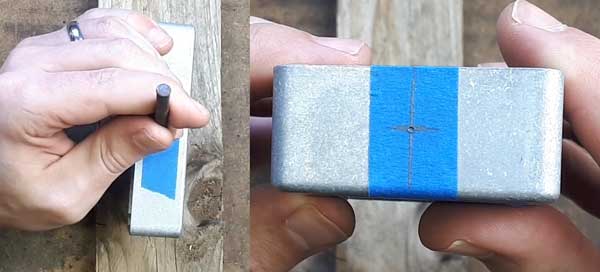
This pedal only has one knob, one LED, and one footswitch, so the face is easy to plan. I simply marked out the positions as I liked the look of as shown below:
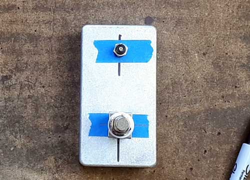
I started by marking a center line on the pedal using a sharpie but realized afterward it would have been easier to put down masking tape and mark everything on that.
When drilling the holes, you can either use a step drill bit (as explained in my DIY Guitar Pedals Guide) or a set of drill bits as shown below:
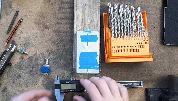
A step drill bit works really well, but you can achieve the same results with a normal set of drill bits.
Before you start drilling, I suggest marking the positions for each hole using a hole punch:
You won’t need to do this if you use a drill press. But if you will be using a handheld drill, the punch will keep your drill bit steady and prevent it from slipping.
If you don’t have a step drill bit, the basic idea is to start with a small drill bit, then gradually work your way up to the full size of the hole. This helps prevent issues or tearouts.
Here’s what the face of my pedal looked like after the first few drill bits:
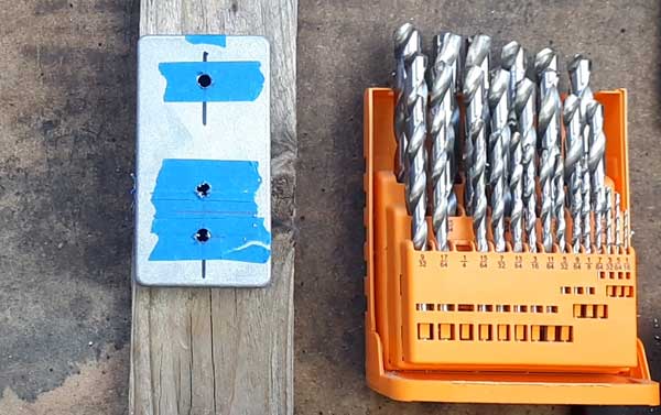
Continue gradually increasing the size of the drill bit until your hardware fits through the holes.
If you will be drilling a pedal with multiple potentiometers, check out my tutorial on building a Fuzz Factory clone as it gives an example of using a drilling template.
Preparing the Pedal Enclosure
There are a lot of different ways you can paint or style your guitar pedal.
The one suggestion I have is to paint or decorate your guitar pedal before you mount your circuit.
The reason I highly recommend painting or styling your pedal before you mount the circuit is that you’re far less likely to do it after you mount the circuit. Jump on any guitar pedal building social media group or forum and you’ll see countless guitar pedal builds with basic raw finishes.
Most of those pedals never get painted or finished because it’s too much effort to undo all of the mounting. So the pedal remains raw and plain.
While there’s nothing wrong with a raw-looking pedal – there are so many better options.
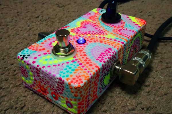
After I drilled my pedal’s holes, I gave the pedal enclosure to a friend to hand-paint. Here’s the end result of patiently waiting for her to finish it:
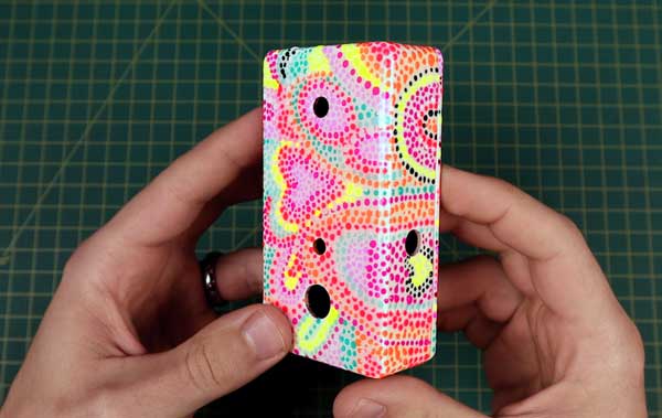
While I had to wait weeks before I could finish my pedal, the reward for my patience is a good-looking pedal (I wanted a hippy-psychedelic design to match the fuzz effect).
I know it’s tempting to jump into mounting your pedal but take the time now to make your pedal look good before you mount the circuit. You’ll be glad you did.
Assembling the Pedal
Once your pedal enclosure is ready for mounting, start by adding all of the hardware into position.
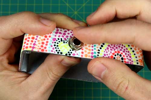
Some people like to wire the circuit up first, then mount it in the pedal. I suggest mounting the hardware first as it makes it easier to figure out the wire lengths you need to connect everything together.
While it will feel cramped trying to solder everything into the small pedal enclosure, you’ll usually end up with better results.
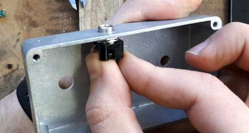
Mount the footswitch as shown below so the holes in the mounting pins line up top to bottom.
Now you can mount the PCB and tighten up all of the nuts.
I suggest only hand-tightening the nuts just in case you need to remove something.
The 7-minute Fuzz kit includes an offboard wiring diagram as shown below:
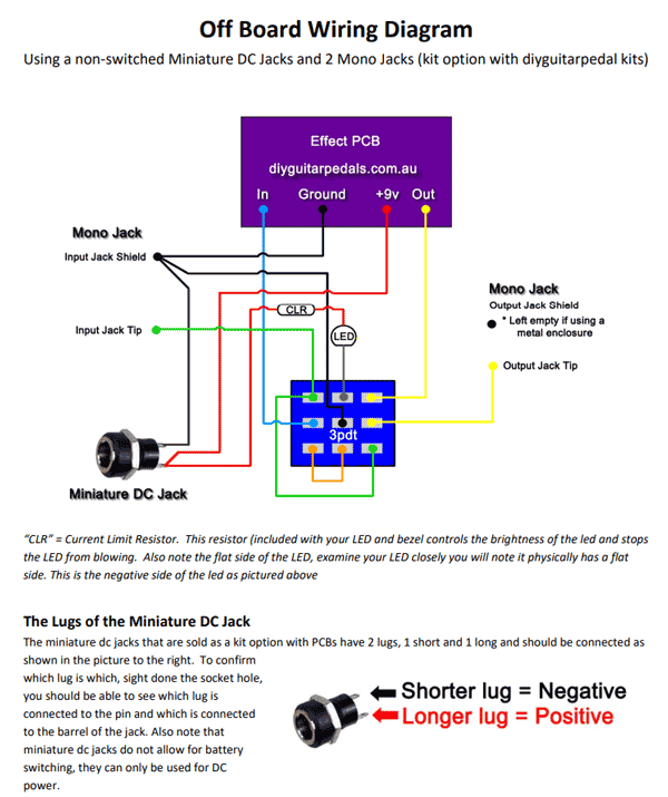
There are a few different ways you can wire a pedal circuit up in an enclosure depending on the LED used, the number of footswitches, the input/output jacks, etc.
As this is a simple circuit, the above diagram is perfect.
If the above diagram looks confusing, just take it one wire at a time.
I started by wiring all of the ground connections together (black wires in diagram). Then I worked my way through the wires one color at a time.
Notice that while the PCB doesn’t use an LED, you can add one to any pedal circuit using the offboard wiring diagram.
All you need to do is connect a current limiting resistor to one leg of the resistor (to prevent it from burning out).
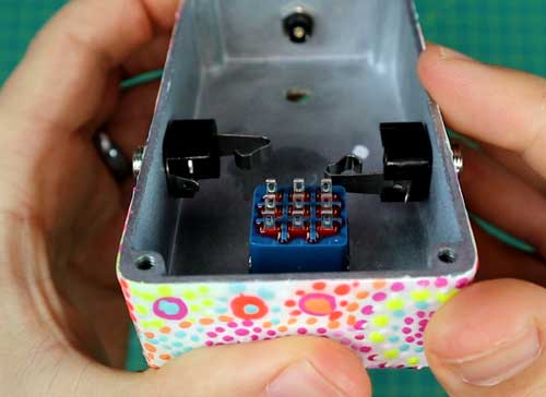
The below photo shows the wiring of the footcontroller. You can see how it matches the above diagram.
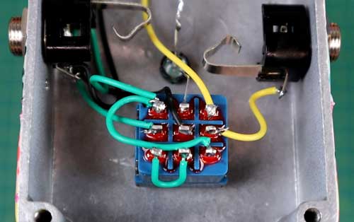
You might notice that the top middle position connects the leg from the LED directly to the footswitch mounting hole. On the other side of the LED I soldered a resistor as you can see in the below photo:
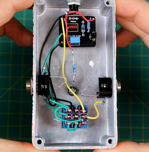
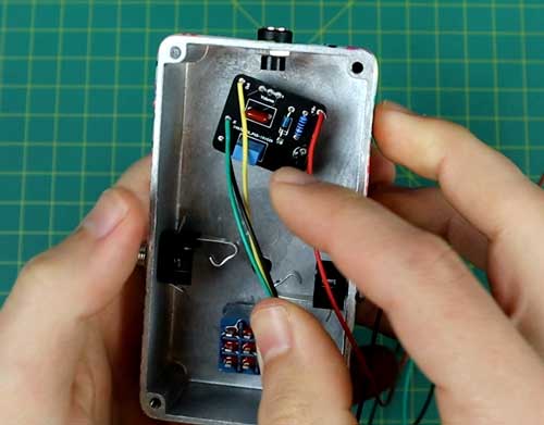
The above photo shows the completed wiring for this kit. If you’re wondering why the other connection on the output jack isn’t connected to anything, it’s because the entire pedal enclosure is connected to ground. So both sleeves of the input and output jacks are connected together by touching the pedal enclosure.
Some people still like to add a wire there, but it isn’t needed.
If you test your pedal and it works, well done! It’s a great feeling when a pedal works on the first attempt.
But don’t stress if it doesn’t work straight away. A short connection or a wire connected to the wrong position can cause weird issues in your pedal’s sound.
If your pedal works, you can now mount the knobs and add the backing plate to the enclosure.
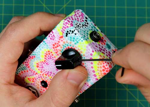
Completed Fuzz Pedal
Here’s the completed 7-Minute Fuzz Pedal connected to an external power supply:
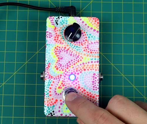
You can see that the LED works when the footswitch is activated. It is possible to wire this pedal up to use a 9V battery, but that requires a different offboard wiring diagram.
Hopefully it’s clear why I suggest building a fuzz pedal like this one as your first build. While there’s a lot to learn when building guitar pedals, this kit uses a very basic circuit.
Starting with a simple circuit will reduce the chances that you run into problems. So build a couple of simple fuzz or drive pedals before you venture out into more complex circuits.
DIY 7-Minute Fuzz Pedal Kit Review
While you probably won’t be able to build this pedal in 7-minutes or even solder the components within 7-minutes, it is one of the easiest pedals you can build.
This was the first pedal I built from a kit and the fact that it only uses a small number of components made it a breeze to work through.
After building this pedal, I felt confident to move on to more complex pedals such as the below Fuzz Factory kit (also available from DIY Guitar Pedals):
If you do buy the 7-minute fuzz kit, I suggest buying the above kit as well (called ‘Berserker Fuzz’) as it’s a great effect that isn’t much harder to build. You can follow this tutorial on building the Berserker Fuzz kit.
As you might expect from a pedal with only one knob to control volume, it’s a very basic sounding effect. You do get that classic fuzz tone, but you don’t have any control over tone or gain level.
The build document includes information on how you can add a gain knob and other mods, so if you’re interested in modding guitar pedals, this kit is a great way to tinker around and learn how to add new features to a pedal.
I highly recommend the 7-minute fuzz pedal kit for anybody interested in getting into building guitar pedals. It’s a simple and cheap kit that teaches you everything you need to know when getting into pedal building.
Hear the 7-Minute Fuzz Pedal
Here’s a video walking through the entire build process as well as a demo of the pedal.
Subscribe to my YouTube channel to stay up to date on new videos like this one.
More DIY Guitar Pedal Tutorials
Building your own guitar pedals can be a great hobby to get into. Here are some more DIY guitar pedal tutorials and guides to check out:
- How to Build a Klon Centaur Clone from a Kit
- How to Build a Fuzz Factory Clone from a Kit
- Ultimate DIY Guitar Pedals Guide
If you find these tutorials helpful, subscribe to my email newsletter to stay up to date on more builds and tutorials.